After years of living in single-room condos, we decided to try a more spacious, two-store house, which has a very old and low-tech doorbell: a button on the door triggers a “ding-dong” classic doorbell - very easy to miss if you are on the upper floor, causing all sorts of issues with deliveries.
Sure, I could make it ring louder, but it would be annoying for anyone on the lower floor. And I also want to automate other hurdles related to package delivery, so I decided to first get the doorbell to ring into my Home Assistant setup (where I can trigger all sorts of automations).
ACϟDC 🤘
The easiest thing would be to replace the front door pushbutton with a four-contact one (so it would close the doorbell circuit and mine); but this being a rental discourages me from doing outdoors modifications; instead I got my trusty multimeter to pry into the doorbell, and found that when the doorbell rings, a ~12V AC current flows through the exposed contacts.
That kind of signal isn’t good to trigger my home automation stuff, which usually relies on Arduino/Raspberry Pi/etc. GPIO pins (which operate on lower voltages and DC current). But the internet is wonderful - I found a circuit that pulls down (that is, connects to GND) a GPIO pin whenever a 12V AC current is present. Here is a reproduction:
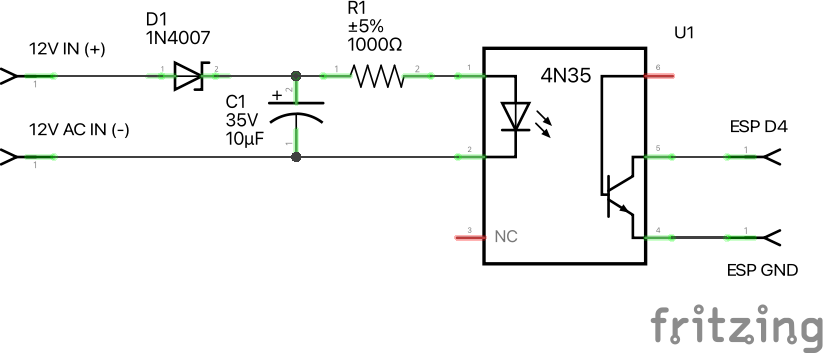
As usual, I’m learning the basics of the electronics involved. This time the big mystery was the AC->DC conversion. What I understood/learned is that:
- The “+” and “-“ refer to the polarity of one of the phases of the alternating current (AC) present when the doorbell is ringing;
- The capacitor charges up during that phase;
- When the current flips, the diode prevents it from flowing, while the capacitor discharges, resulting in a same-polarity, direct current (DC) flow.
The other new thing was the opto-coupler - a tiny chip that contains an LED and a photo-sensitive transistor. Feeding the (now) DC current to the LED closes the transistor, which is a smart way to pull down the GPIO pin while keeping the ESP8266 100% isolated from the doorbell. 🏆
Try before you buy
Before progressing further, I decided to test the circuit above on a breadboard, using an Arduino and a slightly modified version of the 02-Digital/Button example that comes with the Arduino IDE that pulls up the pin and flips the built-in LED when it is pulled down, that is, when the doorbell rings:
void setup() {
  pinMode(2, INPUT_PULLUP);
  pinMode(13, OUTPUT);
}

void loop() {
  int sensorVal = digitalRead(2);
  Serial.println(sensorVal);
  if (sensorVal == HIGH) {
    digitalWrite(13, HIGH);
  } else {
    digitalWrite(13, LOW);
  }
}
Wemos D1 Mini and ESPHome
I could connect that circuit to the Raspberry Pi 3B+ that runs my Home Assistant, but, as I said, it’s a big house, so I got a WeMos D1 Mini - a cheap and tiny ESP8266-based board that, in short, behaves like an Arduino with built-in Wi-Fi.
In the past I used the OpenMQTTGateway software to turn such boards into sensors and triggers. But as much as I love the community around that software, its source-code-based approach and reliance on MQTT makes it quite hard to set up and update.
Enter ESPHome, which is focused on Home Assistant and thus much easier to work with: you just configure what your sensor needs to do in a tiny YAML file straight from Home Assistant; it builds the firmware and updates it (wirelessly and very securely once you set up the first time via USB).
Building for real now
 I know, I know: all the cool kids either make their own PCBs, or design them and use one of the small-volume PCB services that sponsor half of the YouTube electronics videos. Not wanting to deal with the chemicals and iterate quickly, I went to my custom solution of cutting a piece of perfboard and doing the connections with solder and, when needed, jumpers.
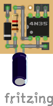
After botching a first attempt (in which I just threw the components at Fritzing’s Breadboard view), I realized I could reproduce the circuit on the Schematic view, and get all the components connected on the Breadboard view, where I could just lay them out on a perfboard (“Stripboard” component) and figure the needed solder/jumper points, error-free - not unlike people use the PCB view to design their boards, I suppose.
I used a white 5V USB charger to power the boards, sticking them with mount tape to the side of the charger (which will be facing down and thus invisible when plugged in):
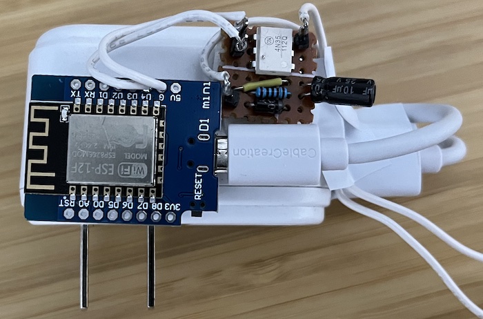
A pair of white wires connects this to the doorbell. It’s not the most finished setup, but it is discreet enough to be ignored (in particular because there are several other white cables running over those walls) and easy to remove when I return this rental.
Here is the link to download the Fritzing (.fzz) schematics:
Making it sing
Using the code above we can check the doorbell state on the ESP8266 LED, but what we really want is to have it available on Home Assistant via ESPHome. The easiest way is to do it directly from Home Assistant, but that requires:
- A browser that supports web serial api (e.g. Chrome); and
- Enough RAM on your Raspberry Pi to build the firmware (my 3B+ has 1GB, which should be enough, but was failing to build until I reinstalled Home Assistant and started fresh - something I wanted to do for a while, since I’ve hacked that instance a lot in the last years).
The specific config that allowed me to get the doorbell state on Home Assistant is:
binary_sensor:
  - platform: gpio
    name: "doorbell"
    pin:
      number: 2
      inverted: true
      mode:
        input: true
        pullup: true
It’s pretty straightforward: we’re using the GPIO pin 2, which is the one we connected to the opto-coupler output, and we’re telling ESPHome to treat it as a binary sensor (i.e. a switch that can be either on or off). The inverted: true is needed because the opto-coupler is pulling down the pin when the doorbell rings, and we want the sensor to be on when the doorbell rings.
Once that configuration is built and installed, we can add/see the sensor on Home Assistant’s dashboard:

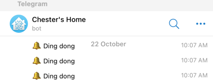
I already had the Telegram bot set up (from this other post), so I just created an automation whose trigger is the doorbell sensor changing from “off” to “on” and whose action is to send a message to my Telegram bot.
I did it mostly on the web UI, resulting in something like this:
alias: Send Telegram message when doorbell rings
description: ""
trigger:
  - platform: state
    entity_id:
      - binary_sensor.doorbell
    from: "off"
    to: "on"
condition: []
action:
  - service: telegram_bot.send_message
    data:
      message: 🔔 Ding dong
      target:
        - 11111111
        - 22222222
        - ....
mode: single
The target:s should be the ID(s) of the user(s) to which the bot will send messages. To get the numeric ID of a Telegram user, you can start a chat with GetIDsBot (source).
Now when someone rings my doorbell, I get a message:
Next steps
As seen above, I often get more than one message; which means that either people are a bit nervous, or I need to set up some debouncing; fortunately ESPHome has options for that.
I also want to figure out a way to check who is on the door (maybe snapping a picture from a security camera and sending it alongside the message), and the icing on the cake would be to open the door (e.g., by interacting with the robot).
Not sure if I’ll do all that (depends on how long I’ll stay on this house), but if I do, it will mean no more packages will be returned or stolen because I wasn’t there to receive them.