- Part I: CPU (6507)
- Part II: Cartridge
- Part III: TIA (Video chip)
- Part IV: Clock and Composite Video
- Part V: RIOT (RAM, I/O, Timer) and Audio
- Part VI: Joystick, switches, fixes and wrapping up
TV Time
In the previous post, I had the CPU, cartridge and TIA wired and tested, but still needed the Arduino to make them tick and check the resuts. All those hex numbers were fun to debug, but let’s get to the real deal: plugging it to the TV.
Clock
In order to show the image of a game on a TV set, the video chip (TIA) needs to generate 60 frames (screens) per second, which, in turn, requires its clock to receive 3,579,545 “pulses” per second. What makes that magic work is a crystal oscilator, and fortunately that particular frequency (3.579545 Mhz) is so common in TV-related applications that one can easily buy such a crystal online.
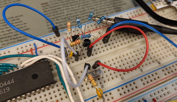
The crystal won’t do the job on its own. We need a circuit that amplifies and cleans the wave it produces, so the TIA gets a more regular signal. Each Atari 2600 model has a slight variation of that circuit, and after fiddling with a couple, I settled on the one used in the Atari 2600 Jr., following this diagram by Kevin Horton:
Testing that circuit was a bit of a pickle: the Arduino could not monitor such a signal. Usually, these tests are done with an oscilloscope. Those appliances were always out of my budget as a hobbyist, but these days there are quite a few “USB oscilloscopes”: they contain the electronics to do the measurement, but output their data to a computer, which makes them much cheaper. Professionals frown a bit on them, but the Hantek 6022BE was within my price range, so I decided to give it a shot.
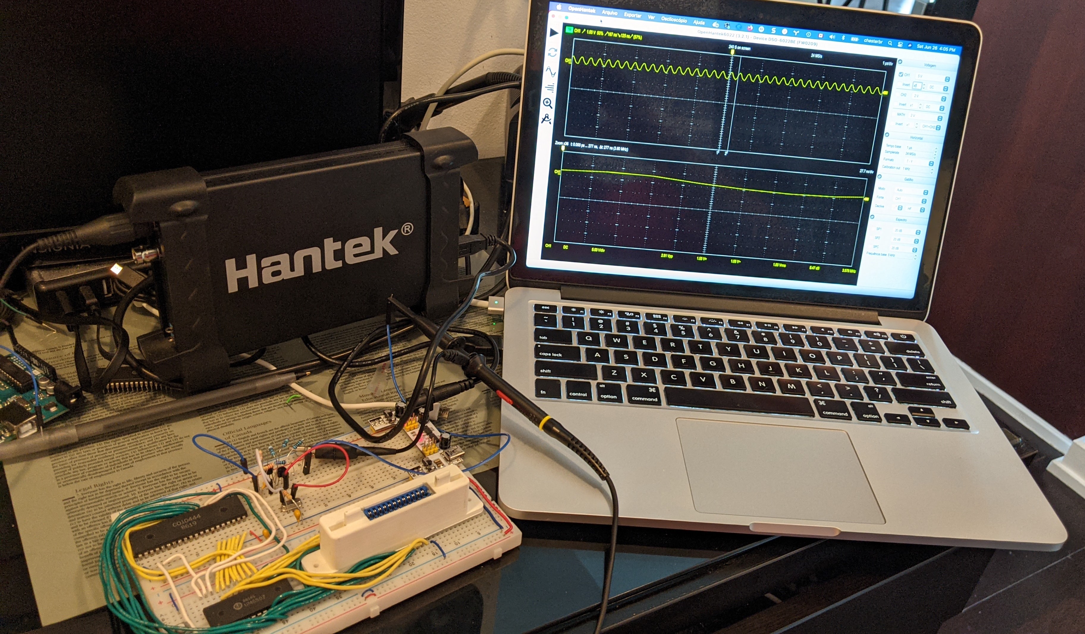
It was a great purchase - in particular due to OpenHantek, an open-source alternative to the included software that future-proofs the investment. The user guide initiated me to the point that I could measure the clock of a working Atari, then compare it with my circuit (click to zoom).

In both cases, I got a steady wave, pulsing once each ~277ns, which the software computes to be a frequency of 3.60 Mhz. The actual values should be 279.365115ns and the 3.579545 Mhz mentioned above, but I had to mark the period manually, and this is as precise as I could get; maybe ther is a way for the software to auto-zoom on a single cycle, have to figure that out.
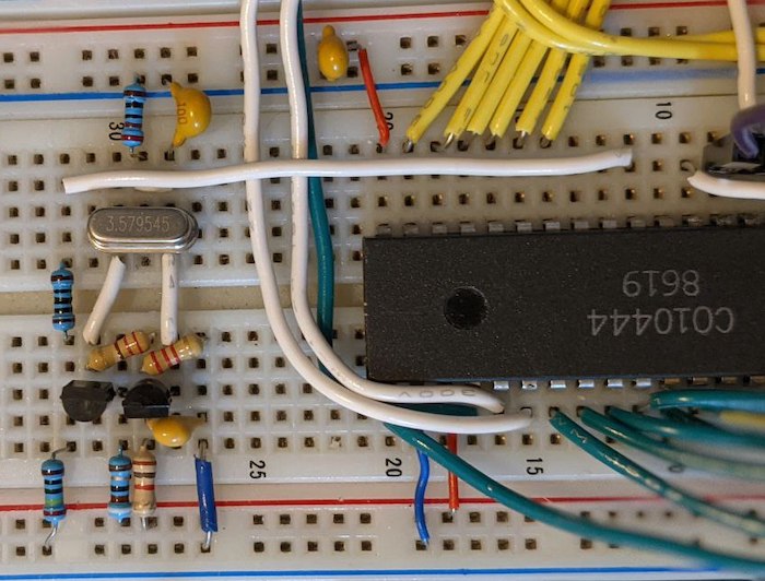
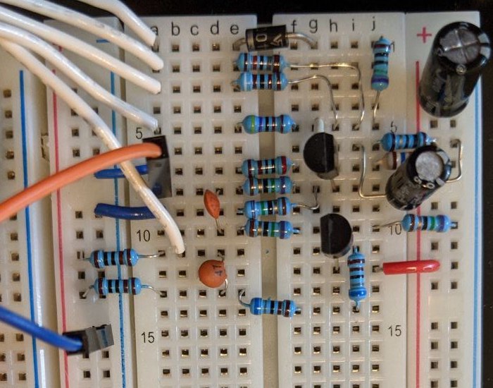
That was enough for me to organize and shorten the components into a tidier circuit. Notice the long horizontal cable connecting the clock output to TIA pin 11, where the Arduino used to provide a much slower pulse.
Composite Video
At that point I had a clock that probably puts the CPU/TIA to work in full speed, so now it’s all about hooking it up to the TV, right? Not so fast: the TIA generates a few separate signals that need to be combined properly into a format that the TV can understand.
The Atari 2600 does so by generating an RF (antenna) signal, which was complicated, prone to interference and most modern TVs have a hard time with it, so a better option for modern TVs is composite video. Roughly speaking, it combines a sync wave (that tells the TV when each frame starts) with the black-and-white and color components (aka “chrominance” and “luminance”) of each pixel (in a non-trivial way to ensure backwards compatibility with black-and-white TVs).

Modern-day Atari owners often install a “composite mod” on their consoles: a small circuit that extracts and combines the signals mentioned above from the Atari main board. I tried using a few mods, but they all depend partially on existing components on the Atari board.
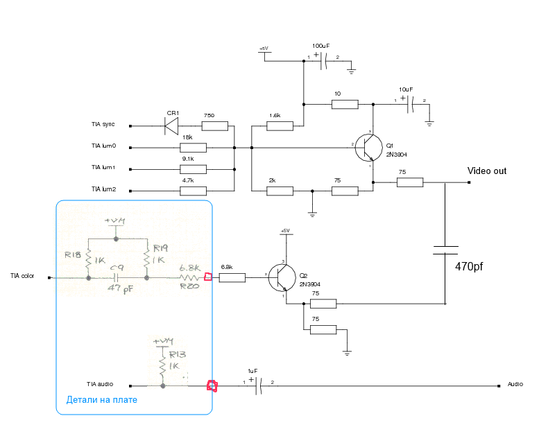
I found a circuit on the AtariAge forum (based on a chroma/luma one from the Atari FAQ) that includes the Atari parts (the ones on the blue border). It’s slightly more complex than others, but was the only one that generated anything on my TV.
Sync issues
Like I did on the previous post, I used the Atari 2600 Hello, World program that I created for an Atari 2600 Programming presentation, because we still don’t have RAM, timers or inputs that any regular game would require. Also, it’s kinda fun to start with a “Hello, World”.
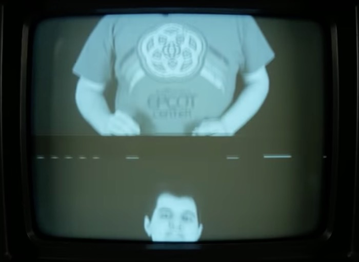
My first attempt (which I livestreamed in Portuguese) was an epic failure (didn’t check for shorts and smell of burning ensued), but the second one worked… if you ignore the lack of color and the rolling screen 😅
This often happens when Atari softare fails to “race the beam”, but that piece of code is, to put it shortly, too minimalistic to fail. After checking the TV menus, I found the issue: the TV was recognizing the signal as PAL, and not NTSC.
Those systems expect different frame sizes, which explains the scrolling (the software sends the next screen starts before the TV is done with the previous one).
TVs of that time were electrical devices, driving a cathode tube that were tied to (among other things) the electrical frequency on the outlets (60Hz in countries that work with NTSC, 50Hz with PAL - which 100% relates to the 50 x 60 frames per second). If you used the wrong frequency, scrolling would indeed happen (if you want details, click the image for a great Technical Connections video about that):
In that context, my modern(ish) TV is more like an “emulator”, trying to identify and decode the signal into its LCD array of fixed pixels. That is hit-and-miss (of the three TVs that I tested, this was the only one that showed any image at all). I tried adding a CD4050 chip as a buffer (like the FAQ circuit does), no improvement.
The fix => HELLO, WORLD!
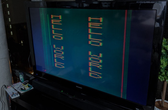
What actually worked was “cleaning up” the circuit - cutting the components and fitting them properly (like I did with the clock). That convinced the TV to recognize the signal as NTSC. Swapping the crystal also gave it more stability (maybe the livestream incident broke it? glad I bought a pack of 3 😅).
Anyway, I finally got to the first milestone I envisioned where I started this journey, years ago: HELLO WORLD! 🎉
Next steps
Even with the fixed circuit, the image is a bit unstable, colors are wrong and there is an odd bar on the right. But instead of debugging these, I’ll add the RIOT (the last chip), which should allow me to run actual games and fine-tune the circuit.
I also want to update the Fritzing sketches with all those circuits once I settle them (so anyone wanting to rebuild a custom Atari can have a more readable starting point), add or build a controller… we’ll see!