- Part I: CPU (6507)
- Part II: Cartridge
- Part III: TIA (Video chip)
- Part IV: Clock and Composite Video
- Part V: RIOT (RAM, I/O, Timer) and Audio
- Part VI: Joystick, switches, fixes and wrapping up
After Hello World
Now that I got Hello, World! running, I feel confident this project may actually succeed! 😅 The next step is to run an actual game, which requires wiring the last chip (and, due to the poor video I have so far, a sound circuit).
Adding RIOT
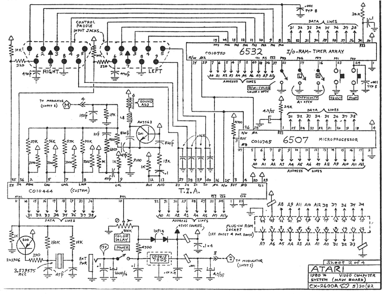
MOS’s catalog included several support chips compatible with its successful 6502 “family” of CPUs (of which our Atari’s 6507 is a member). Atari picked the 6532 to supply the missing pieces (RAM, Input/Output channels and Timers) that give this chip the nickname “RIOT”.
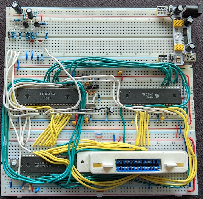
Wiring it was no different than wiring the TIA. Pretty much:
- Following the address and data lines from the schematics;
- Connecting the +5V (1) and ground (20) pins to their power rails;
- Bringing the RESET (34) pin up - the schematics have a 24K resistor and a .1µF capacitor that I considered overkill, but heck, why not;
- Connecting the 6502 Phase 2 clock (𝜃2) clock and R/W pins (28 and 26) to its RIOT counterparts (39 and 35), so the CPU can sync the communication with the chip.
The chip also reads directional/fire buttons from joysticks, SELECT, START and both difficulty switches, but I’ll wire those later. All I want is to give games what they need to run!
Some sound
Sound was actually part of TIA, but I did not bother adding it before because the only software I had that would work without RAM and Timers (the “Hello, World” program) was silent. But now it will work (and be invaluable since my composite output is still 💩), so I added a 1K resistor and a 1µF cap to both pins; resistor goes to 5V and cap goes to center pin of audio jack (outer part is ground). May be improved (e.g., doubling the circuit for “stereo” sound), but good for now.
Games!
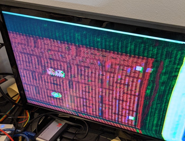
Incredibly, this setup worked first time (notwithstanding the video). One can hear (and almost see) Pac-Man going through the circle of life:
Video blues
Unfortunately, I can’t still get a good composite video image. Tried every composite circuit under the sun, results are still wonky. The best I got so far was with the circuit mentioned on the last post, only replacing a resistor that was a bit out-of-range:
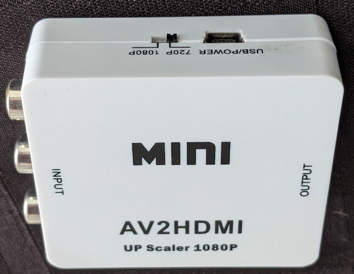
In fact, only one of my TVs got me any image at all (as previously mentioned, modern TVs are more picky with the signals they get). People often get around that running the signal through a VCR, but I had a much smaller option: this composite-to-HDMI converter. It’s not as tolerant as the VCR (or a tube TV), but it picks up even this bad signal, and was quite cheap when I bought it.
Next
I guess I should now add a joystick and SELECT/START (either a connector, or some push buttons, depending on what I have on my drawer), then fix the video (assuming it’s not a TIA defect). Then I’ll transcribe all the things back to a Fritzing drawing (so anyone - including myself in the future - can reproduce), and I guess I will be done with this experiment.