- Part I: CPU (6507)
- Part II: Cartridge
- Part III: TIA (Video chip)
- Part IV: Clock and Composite Video
- Part V: RIOT (RAM, I/O, Timer) and Audio
- Part VI: Joystick, switches, fixes and wrapping up
Previously…
A long time ago I grabbed the three chips from a broken Atari 2600 (Jr.), to see if I could build an Atari with them on a solder-less “breadboard”. My first attempt (post here) was to drive the CPU with an Arduino, which showed the chip advancing through what it believes to be memory, but is actually just a single “no operation” (NOP) hard-wired instruction:
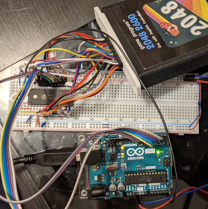
It took some time (between finding the right connector, 3D-printing a part, figuring out the wiring and fixing the Arduino software), but I finally moved on to the next step: plugging a real Atari cart and seeing some actual code running!
How the Atari 2600 reads game carts
An Atari cartridge contains a ROM (Read-Only Memory) chip, meaning we’ll only read data from it. The 6507 CPU can request any single byte on a given memory position on the cart by setting that memory address, in binary form, on a given set of its pins (the address bus), and the cart responds with the byte on that position on another set of pins (the data bus).
In fact, these buses are used to both read and write bytes to all other parts of the system, but for now we only care about the cart. My first step was to get the cart pinout, which you can find in several places, but people often forget to mention the orientation of the pins, whether we are seeing the cart or the slot, etc., so I went with the original Atari schematics, which shows the connector as seen by someone looking directly at the console:
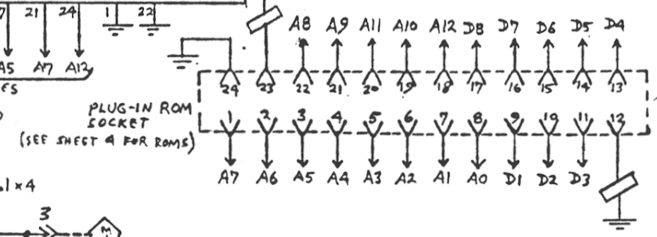
From looking at it, the connector consists pretty much in address (A0-A12) and data (D1-D8) lines (plus a +5V and two GND pins), so connecting those to the matching CPU and voltage pins in our board should do the job, no extra electronics needed this time.
Physical connection
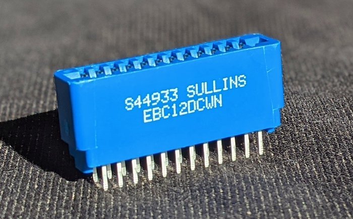
In non-Atari lingo, the socket is a 24-pin “edge” connector - which is just like a computer peripheral card “slot”, only smaller. It isn’t a trivial size, but with the right name you can find it online (or use the link above).
Unfortunately you can’t just plug a cart into the connector, because carts (or, at least, the Atari-manufactured ones) have a sliding plastic protector that only opens when the cart is inserted in the matching plastic guide - and that one isn’t manufactured anymore.
I was lucky not to be the only one with this problem. In particular, people hacking Atari Flashback mini-consoles to add a cart slot also required one, so they created a model that I could download and 3D-print (of course, there are other options you may consider):
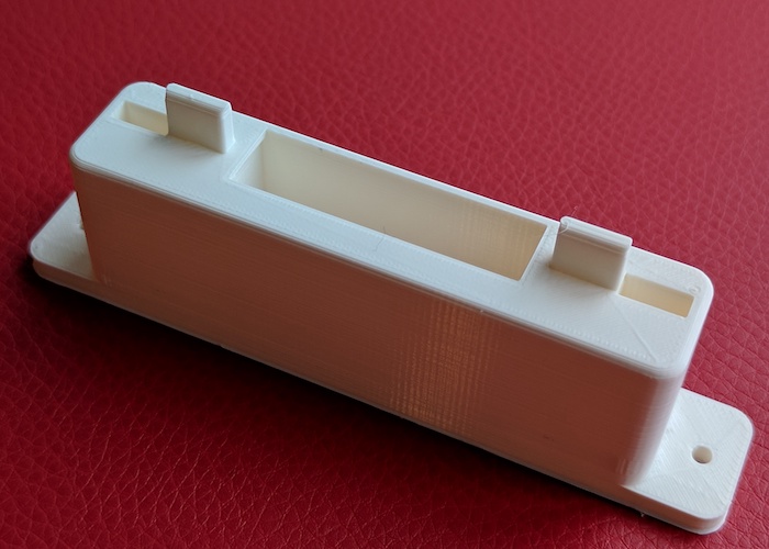
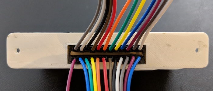
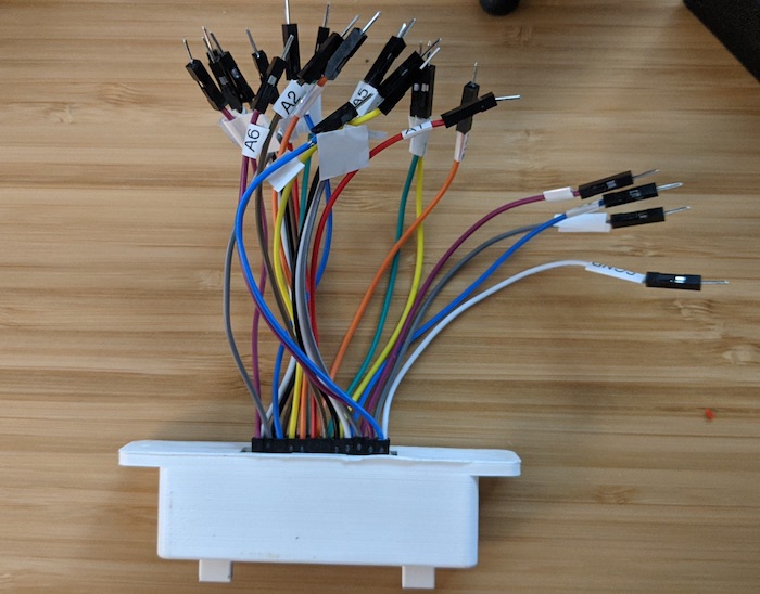
The fit wasn’t perfect, but with some epoxy and a bit of drilling, I managed to fix the connector in the guide. I connected some female-to-male jump wires (hint: use longer ones), inserting a toothpick to keep them firm, then labeling according to the schematics:
Wiring
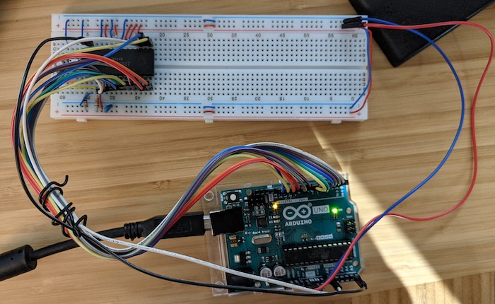
Starting with the breadboard from the first post, I removed the hard-wired NOP instruction, and connected the address/data lines to the matching pins on the 6507, and the +5V (socket pin 23) and ground (socket pins 12 & 24) to the power lines.
One thing to notice: the Atari schematics refer to data pins as D1-D8, whereas 6507 names them D0-D7 (starting from 0 like the address pins, and also like bits are usually assigned). But at least they are aligned on the chip, so it wasn’t (much) confusing.
Another thing to pay attention: for some reason, A10 and A11 are flipped on the connector - the sequence, looking left-to-right from outside the console, is A8, A9, A11, A10 and A12. Remember to flip them as you connect the wires.
Speaking of pins, the previous method of monitoring the address lines worked fine when addresses were just growing sequentially, but monitoring an actual program this way was too difficult, so I switched to wiring the Arduino to the data lines instead. That will show the actual ROM bytes as they were requested by the CPU for execution (as long as we tweak the monitoring program, which I had to do anyway, see below).
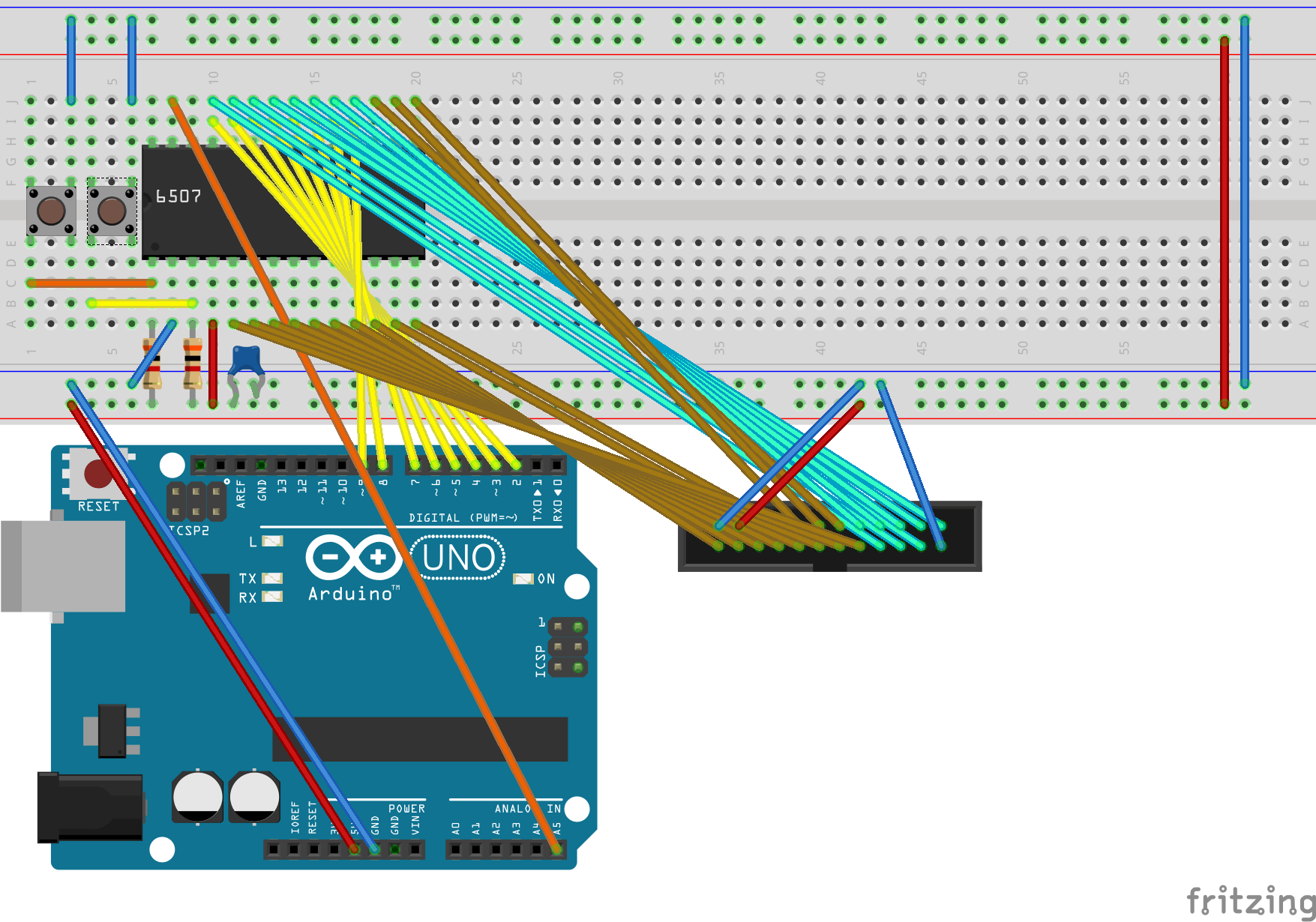
Here is the updated drawing, with the Arduino connected to the data lines, and the cart connected to data and address. I included the power connections as well, so everything needed is there. I recommend opening the .fzz file on Fritzing, which has the pin names on the cart connector (it doesn’t resemble the connector a lot, I know; but it’s the first time I customized a part in the software).
Monitoring
The test program generates a (slow - 10Hz) clock pulse to keep the processor running. At each pulse, it prints the hex value from the data bus in the Arduino IDE serial monitor (set the speed to 115200). It is much smaller than the original code, and several issues (such as use of serial I/O pins and wonky binary conversion) were fixed.
// Turns an Arduino into a 10Hz clock generator (on pin A5)
// and a monitor for an 8-bit data bus (pins 2-9)

void setup() {
  for(int pin = 2; pin <= 9; pin++) {
    pinMode(pin, INPUT);
  }
  pinMode(A5, OUTPUT);
  Serial.begin(115200);
}

void loop() {
  // Clock pulse
  digitalWrite(A5, HIGH);
  delay(50);
  digitalWrite(A5, LOW);
  delay(50);

  // Print current data bus (pins 2-9)
  int data_value = 0;
  int power_of_two = 1;
  for(int bit = 0; bit <= 7; bit++) {
    data_value += digitalRead(bit + 2) * power_of_two;
    power_of_two *= 2;
  }
  if (data_value < 0x10) { Serial.print("0"); }
  Serial.println(data_value, HEX);
}
Let’s run some Atari code!
To test it, I’ve used a cart with 2048 2600 since, as the author, I’m familiar with the code. The Stella screenshot below shows the initialization code, and we’ll be looking for the bytes (opcodes) on the right side:
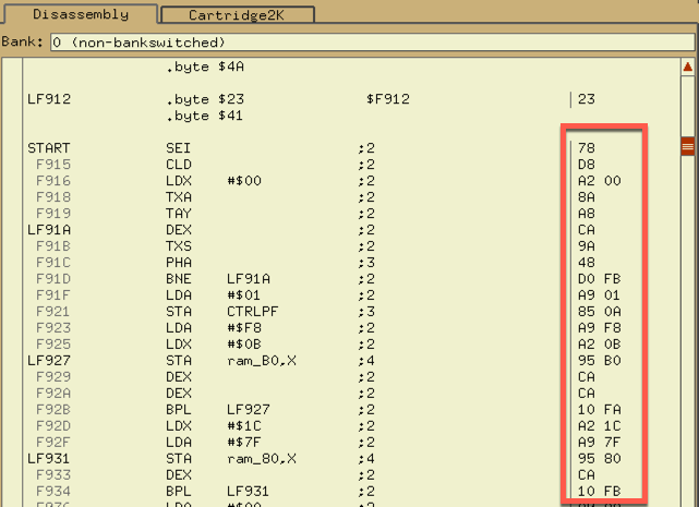
To be precise: once we press and release the “reset” push button, we expect the 6507 to read the address of that code (F914) from its standard location from the cartridge, then start reading the opcodes above (78, D8, A2, 00, …) in sequence, until the BNE instruction at F91D loops back to reading again from a few lines above (CA, 9A, 48, …), and repeat that a bunch of times.
That will be enough to show us whether this mess of wires is working - and indeed it is! Check this snippet of the serial monitor output (comments and disassembly after #), comparing to the values above:
...
00                  # Some gibberish here, until 6507 resets
00
14                  # 6507 reads the contents of RESET vector: the lowest byte (14)...
F9                  # ...then the highest (F9) of F914, which is where our code starts
78    # SEI         # read from address F914
D8    # CLD         # read from address F915
D8
A2    # LDX #$      # read from address F916
A2
00    #       00
8A    # TXA         # read from address F918
A8    # TAY         # read from address F919
A8
CA    # DEX         # read from address F91A
CA
9A    # TXS         # read from address F91B
9A
48    # PHA         # read from address F91C
48
D0                  # maybe a premature read of next instruction?
00                  # the value that would be sent to the stack - if we had RAM :-)
D0    # BNE
FB    #      F91A   # address calculated as "5 bytes before"; FB here means -5
A9
CA    # DEX         # again from address F91A
9A    # TXS         # again from address F91B
9A                  # ...
48
48
D0
00
D0
FB
A9
CA
9A
...
We print the value on the data bus once per clock cycle - since instructions take a different number of clock cycles to run, we see the uneven repetitions. But overall, we are running the code in the cart - mission accomplished! 🎉
Next steps
Hope I don’t take as long as I did this time to continue with this experiment. I wonder if I can add the TIA at some capacity without going with a full speed clock (which will be hard to monitor without an oscilloscope, so I’m deferring as much as I can). I’ll see as I tinker. Stay tuned!