- Part I: CPU (6507)
- Part II: Cartridge
- Part III: TIA (Video chip)
- Part IV: Clock and Composite Video
- Part V: RIOT (RAM, I/O, Timer) and Audio
- Part VI: Joystick, switches, fixes and wrapping up
It has been a wild ride, and it finally comes to an end. Here are the final tweaks I’ve added to this project, which results in a mostly working Atari 2600. Most importantly, I learned a ton and had a lot of fun. If you came so far, I hope you did too!
Joysticks
It’s time to play, and for that we need a joystick! I could a couple DB-9 connectors, but it was more fun to just add a few push buttons and precariously play by pressing them directly on the motherboard.
The Atari joystick connector has a pin for each direction and the button, open by default. When you move or press, the controller closes the connection between that pin and ground. A simple design that requires no electronics on the joystick itself (paddles and auto-fire are another story, of course).
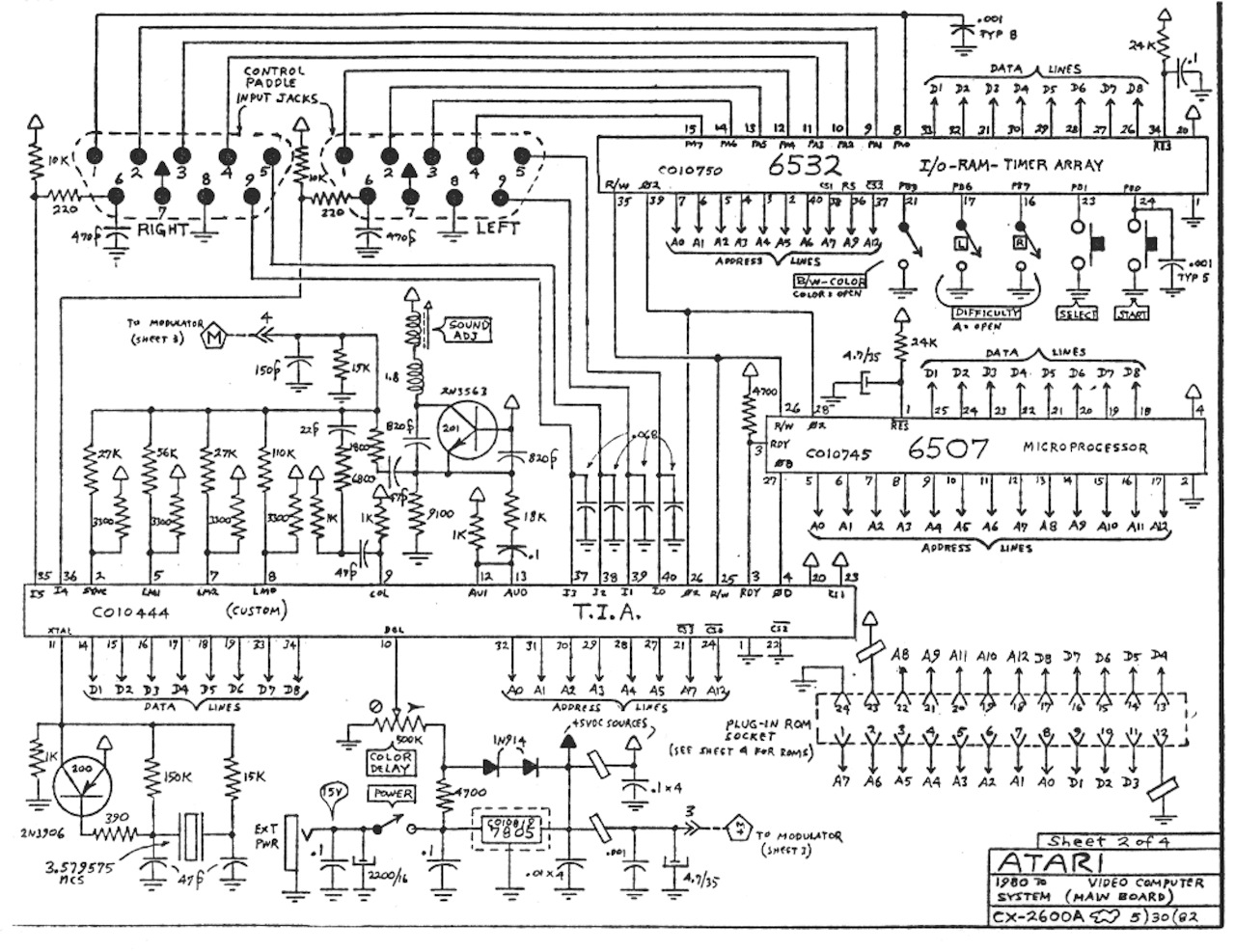
Directions are handled by RIOT pins 12-15 (PA4-PA7), so I just connected them to the push buttons (black wiring). The fire button is handled by TIA pin 36 (I4), but it requires what seems to be debouncing circuit (a high-value resistor pulls it up, and a capcitor/low-value resistor ensures consistent registering of button presses).
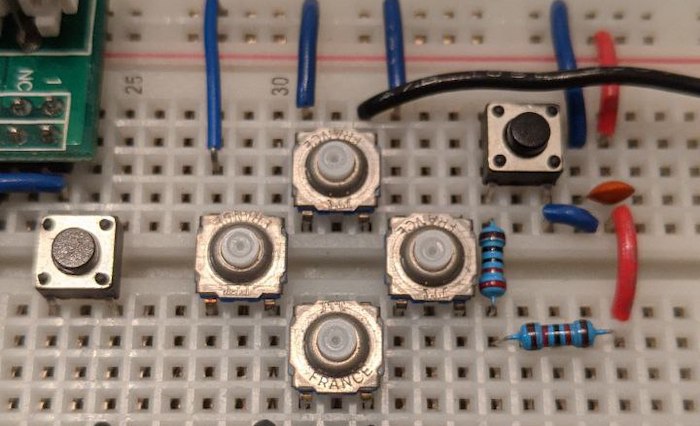
I did not connect the buttons for a player 2, but it would be the same thing, using using RIOT pins 8-11 (PA0-PA3) and TIA pin 35 (I5). I did have to add the pull-up resistor to the TIA pin, otherwise player 2 would fire constantly. Likewise I don’t care about the paddle pins, so I just added capacitors to TIA pins 37-40 to avoid spurious signals.
Console Switches
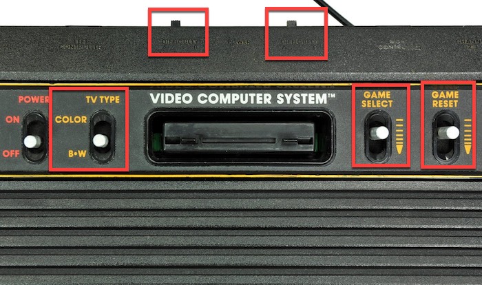
The Atari 2600 had quite a few switches on the console: two difficulty switches (one for each player), TV Type, Game Select and Game Reset . They are all handled by a subset of RIOT pins PB0-PB7.
For this experiment, I only needed Game Reset to play, so I added a push button between that one (pin 24/PB0) and ground, with a (debouncing?) cap like in the original schematics, and let all the others open. It’s the leftmost black button seen on the picture above.
This was the last “feature”, but I still had a couple things to fix:
Consistent power on
One thing that bothered me was that the breadboard Atari would never power on cleanly - most games would just crash, and I’d have to push the 6502 reset button a couple times to make it start properly.
That happens because the 65xx family of processors doesn’t have a built-in startup circuit - when powered on, the CPU just works with whatever (usually bad) state the silicon happens to be on.
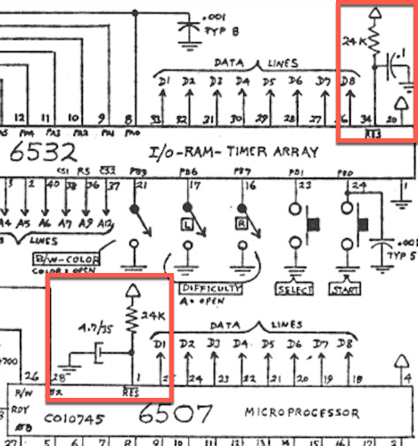
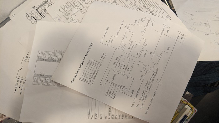
The original schematics shows a 4.7µf capacitor alongside a pull-up resistor do the job of triggering the reset once the capacitor charges, which not only ensures the proper initialization, but also gives time for the CPU to start its work at optimal power level.
I had the pull-up resistor in my drawer, but not the capacitor at that exact value. Didn’t matter: a higher value just delays power-on by a non-humanly-measurable factor, so I threw in the 100µf I had. Now the Atari turns on consistently whenever I power it. For good measure, I added the equivalent circuit for the RIOT (6532), since it also shows up on the schematics:
Display vertical alignment
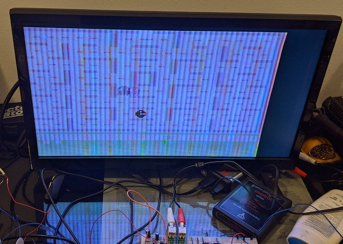
In previous posts, I tried several composite circuit variations, but I’d always get a scrolling image, like the TV wasn’t able to figure out when each frame (“screen”) started. After a lot of head-scratching, I finally found the issue: TIA pin 6 (BLK), the “Vertical Blank Output” - that is, the signal that is output at the beginning of every frame of an Atari game, is not connected anywhere.
For some odd reason, it doesn’t appear on the Atari schematics. Once I joined that pin with pin 2 (SYNC), a stable image appeared! Horizontal position and weird colors still need adjustment, but that can be solved by fiddling with resistor values on the composite circuit. For my study purposes, it’s good enough™️:
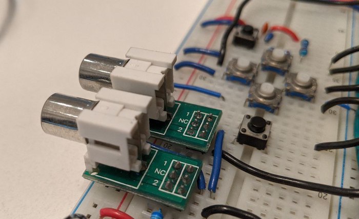
I also got a pair of RCA jacks for breadboards from Omega MCU Systems - they have breadboard connectors for all sorts of things, making connections to the outside world much sturdier.
Wrapping it up
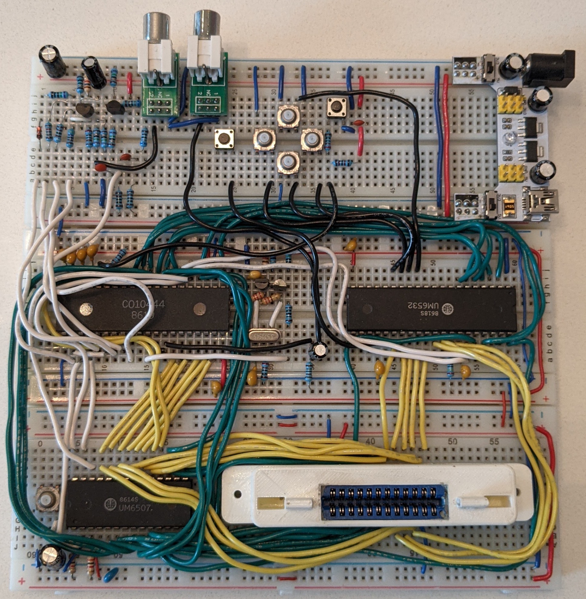
With that setup, all my carts worked pretty well - including the Harmony Cart, that allowed me to test all sorts of games; including modern homebrew!
Below is the final board (and here is a larger photo). It required connecting three breadboards together:
- Bottom board has the 6507 CPU and the cart connector
- Middle board has the TIA, clock, sound and RIOT (the later in the opposite direction to simplify the data lines coming from the cartridge)
- Top board has the composite video circuit, audio/video connector, joystick/RESET buttons and a power adaptor.
Wires are somewhat color-coded: red/blue for power/ground, yellow for data lines, green for address lines, white for logic signals (clock, chip select, read/write, etc.) and black for input/output devices (audio/video/controller).
Final considerations
My main motivation for this project was the fact that I wanted to reproduce Ben Heck’s hand-soldered Atari, but he did not publish any diagrams (like he usually does), just referring people to the original Atari schematics (which were near uncomprehensible for me at the time).
My plan was to create drawings of the breadboard on Fritzing as I progressed, so anyone wanting to rebuild an Atari could do so without resorting to the circuit diagram. And I did it on the fist few parts, but at certain point, it became impossible - the drawing got too complicated and Fritzing started to crash.
Anyway, after tackling the project in small steps (and looking at other diagrams, partial circuits, articles and discussions), I learned enough about electronics and the Atari 2600 to grasp its original diagram - and finally understood why Ben did not find it necessary to publish anything else.
So if you want to (re)build your ow your Atari, be it soldered or on a breadboard, you can either follow the diagram like Ben, or, if it’s too complicated, just go step by step.
In any case, I hope you have as much fun (and learn as much) as I did!
Comments
manotroll
is there any project to replace the atari processor for another more modern processor only at the same cost?
chesterbr
Not that I know of - the Atari 7800 technically replaced the CPU with a 65c02(-ish); but it had to be kept at the same speed for compatibility; any such replacement would also have the same constraint (as the timing would be tight); so it's hard to see an advantage in such a replacement.
manotroll
but in terms of costs looking for the separate components the value is a little high for an atari